
Thread forming taps: what drill size to use
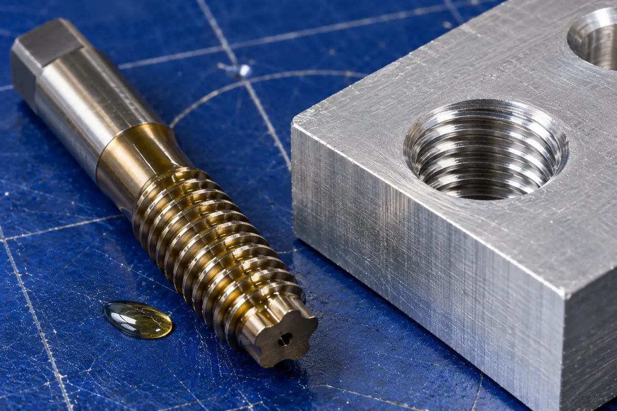
A thread forming tap pushes metal into a thread instead of cutting it out. Because nothing is removed, the displaced metal has to go somewhere, and it flows inward toward the center of the hole. So a forming tap needs a much larger hole than a cutting tap for the same thread. Use a cutting-tap chart with a forming tap and the tap will usually seize or snap.
How forming taps work
EMUGE-FRANKEN describes it plainly: unlike thread cutting, no material is removed during thread forming; the process displaces material to make the thread form.[1] The tap has lobes instead of cutting edges. Tapmatic adds that it has neither flutes nor cutting edges, so it makes no chips, and that the grain of the metal follows the contour of the thread, as in a good forging.[2] The metal pushed out of the thread groove rises to form the crest of the thread, which is why the starting hole must be larger.
The drill size formula
The forming formula looks like the cutting one with a different constant. Tapmatic gives it as:[3]
Forming drill = basic tap OD − (0.0068 × % of thread ÷ threads per inch)
Missouri Carbide uses the same inch formula and gives a metric version:[4]
Forming drill (mm) = basic tap OD (mm) − (% of thread × pitch ÷ 147.06)
Harvey Performance prints the identical inch formula,[5] and KAR Industrial uses both constants on its forming tap chart.[6] One divided by 147.06 is 0.0068, so the inch and metric versions match.
The constant is about half the cutting-tap value of 0.01299. In effect, for the same percentage, the forming hole is drilled about half as far below the major diameter.
The hole size window
Missouri Carbide gives a simple maximum and minimum:[4]
Inch: maximum drill = D − 3/(8 × TPI); minimum drill = D − 1/(2 × TPI)
Metric: maximum = D − 0.375P; minimum = D − 0.5P
It describes these as about 55% (maximum drill) and 75% (minimum drill) of thread.[4] Dan Gajdosik, a senior engineer at Besly Products writing in Cutting Tool Engineering, says roll-form tapping is not recommended above 75% thread, because there is no room for the material to flow.[7] So the useful range for forming is roughly 55 to 75%, lower than the cutting-tap norm.
BAER, a German tool supplier, uses a slightly different metric rule: D − 0.5P + 0.05 mm.[8] That is 0.05 mm larger than Missouri Carbide's minimum.
Worked examples
1/4-20 at 65%
0.250 − (0.0068 × 65 ÷ 20) = 0.250 − 0.0221 = 0.2279 in, a #1 drill (0.2280 in)
Missouri Carbide's window: 0.250 − 3/160 = 0.2313 in (max) to 0.250 − 1/40 = 0.2250 in (min)
Compare the cutting tap's #7, at 0.2010 in. The forming hole is 0.027 in larger.
Missouri Carbide works this same example to 0.2279 in.[4]
M8 x 1.25 at 65%
8 − (65 × 1.25 ÷ 147.06) = 8 − 0.553 = 7.45 mm
Window: 8 − 0.469 = 7.53 mm (max) to 8 − 0.625 = 7.375 mm (min)
BAER's rule: 8 − 0.625 + 0.05 = 7.425 mm
KAR Industrial's chart gives the same 7.45 mm.[6] The cutting tap for M8 x 1.25 takes 6.8 mm.
M6 x 1 at 75%
6 − 75 ÷ 147.06 = 5.49 mm, so a 5.5 mm drill
KAR's chart lists 5.5 mm for M6 at 75%.[6]
Why the hole is so critical
A cutting tap tolerates a sloppy hole; a forming tap does not. Pat Nehls of Walter USA gave Cutting Tool Engineering an M4 example: a cutting tap can use a 0.130 in hole with a tolerance of +0.005/−0.002 in, while a forming tap needs a 0.1457 in hole held to ±0.0012 in.[9] Too small, and the displaced metal has nowhere to go: torque soars and the tap can break. Too large, and there is not enough material to fill the crest of the thread.[9]
Missouri Carbide admits there is no way to predict the finished percentage exactly because so many variables are involved.[4] The practical answer, from Haas's tap chart, is to measure the minor diameter after form tapping and adjust the drill size as needed.[10]
Forming taps also commonly carry a larger pitch-diameter limit than cutting taps, H6 against H5 for a 1/4-20 class 2B tap, according to Peter Gennuso of OSG.[9] Do not swap a cutting tap's limit for a forming tap's.
Which materials can be form tapped
Forming works in metals that flow. Tapmatic's list includes low-carbon steels, leaded steels, austenitic stainless steels, low-silicon aluminum die-casting alloys, ductile wrought aluminum, zinc die-casting alloys, and ductile copper alloys and brasses.[2] EMUGE-FRANKEN's quick test: materials that produce a continuous chip when drilled are good candidates.[1]
Brittle materials do not work. Cutting Tool Engineering states that brittle materials such as cast iron do not flow well and cannot be form tapped.[9] Sources differ on the hardness limit:
- Gajdosik: at least 8% elongation and no harder than RC 30.[7]
- Bob Warfield and the CTE feature quoting Walter, OSG and KOMET: about 36 HRC.[11][9]
- EMUGE-FRANKEN: tensile strength up to 1200 N/mm² and hardness below about RC 35 to 40.[1]
Work-hardening metals need sharp drills. Tapmatic warns that surface damage from a dull drill can raise torque to the point of stalling the machine or breaking the tap.[2]
The crest seam
Because the crest is formed from metal flowing up from both sides, it can close with a small groove in the middle. Peter Gennuso of OSG describes it as a little channel, or void, inside the thread crest that can hold contaminants.[9] Warfield notes some industries ban form taps for that reason.[11] For most mechanical work it does not matter; for medical, food or high-purity systems, check the specification first.
Lubrication and running speed
Lubrication matters more than cooling. Missouri Carbide says it is more important to lubricate a forming tap than to cool it and does not recommend soluble oils; Tapmatic says to use a good cutting oil or lubricant rather than a coolant.[4][2] Gajdosik warns that with no fluid the tap can weld itself inside the hole.[7]
Torque figures vary widely. OSG's Gennuso says form tapping takes two to four times the torque of cutting.[9] Tapmatic says that at 75% thread or less, the extra torque ranges from none to 50% depending on the material.[2] Gajdosik puts it at anywhere from none to more than three times.[7] Speeds are higher than for cutting taps: Missouri Carbide recommends 1-1/2 to 2 times the cutting-tap speed.[4]
In blind holes, plan extra depth. Missouri Carbide's bottom chamfer needs a hole drilled 3 to 4 pitches beyond the full thread.[4]
Are formed threads stronger?
Sources say yes, but none of the ones checked here publishes test data. EMUGE-FRANKEN says formed threads are generally stronger and have a smooth, burnished finish,[1] and a CTE feature cites Machinery's Handbook on unbroken grain and work hardening.[9] Warfield adds a caution that form tapping can also leave stress risers on the threads.[11] The taps themselves are stronger than cutting taps, with a larger cross section,[11] and Wikipedia notes they can last 3 to 20 times longer.[12]
Common mistakes
- Using a cutting-tap drill. The hole is far too small for the metal to flow, and the tap seizes.
- Aiming for 75% or more. Makers set 75% as the ceiling for forming.[7]
- Form tapping cast iron. It crumbles instead of flowing.[9]
- Running dry or with soluble coolant. Use oil.[4][7]
- Trusting the formula without checking. Measure the minor diameter of the first parts and adjust.[10]
The tap drill calculator has a forming-tap mode that uses the 0.0068 constant and lists the nearest stock drills.
Sources
- Cold-Forming Taps, EMUGE-FRANKEN AB
- Machine Recommendations for Cold Forming Taps, Tapmatic
- Tapping Formulas, Tapmatic
- Engineering Data: Thread Forming Taps, Missouri Carbide
- 8 Unique Facts About Thread Forming Taps, Harvey Performance
- Tap Drill Sizes for Forming Taps, KAR Industrial
- Threads Will Roll, Dan Gajdosik, Cutting Tool Engineering
- Core hole dimensions for screw taps, BAER
- Chuck the chips, Susan Woods, Cutting Tool Engineering (2013)
- Tap sizes chart (form tapping), Haas Automation
- Seven Ways to Avoid Breaking Taps, Bob Warfield, Cutting Tool Engineering (2022)
- Tap and die, Wikipedia
Found an error? Email [email protected]. Our editorial policy explains how guides are researched and corrected.
 Thread forming tap
 Tapping oil
 Pin gauge set